Motion Sensor Control Motion Detector Trigger
Version: 1.1
Last Update : 10/19/2009
This document contains notes
to myself that allowed me to construct the motion sensor control. Instructions within this document are notes
to myself and recommend steps to myself. Anyone using this document to
construct a motion sensor control does so at their own risk.
Beware;
this document is intended only for people with electrical and electronic
project skills and the knowledge of the involved hazards to property and to
life forms including people, and the necessary safety procedures. Use the
information here only at your own risk.
The
use of the motion sensor control is at the
user's sole risk. By purchasing the components to build the motion sensor control, the purchaser/builder
understands that the motion sensor
control
is intended for educational purposes and any use of this information,
components, or completed project is at the users own risk. The
creator/supplier of this information and components shall not be liable for any
damages or personal injury from the use of the motion sensor control.
Then store bought motion
sensor has specific specifications that should be adhered to, namely the
control is rated 120v AC, 60hz, 4.2amps, max 300-500 watts depending on the
sensor. The project is using a house hold extension cord. The household
extension cord is a 16 gauge wire, two conductor (no ground) rated 125v, 1625
watts. Here are some extension cord safety tips - http://www.cpsc.gov/cpscpub/pubs/16.html
The information contained in this document is not to
be redistributed.
Tools Required
Note: not all tools may be
required if some of the components have already been prepared.
Phillips Screw
Driver
Black Tape
Wire Cutters
Wire Strippers
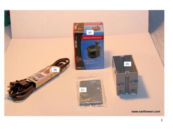
Components - Supply List ($20)
Reference Figure 1 for a
picture of each component. Note: not all components will look exactly like what
is pictured in this document. The outlet box might be a different color, the extension
cord might be a different color, length, etc. This goes for all of the
components.
(A) 1 single
outlet box (gang box, wall box) ($1)
(C) 1 - outlet box
cover (.50)
(D) 1 - extension
cord 125VAC, 16/2 gauge ($1)
(Z) 1 Replacement
Motion Sensor (detector) ($10-13)
Prices are approximations.
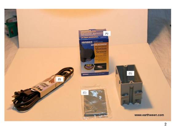
Motion sensor can be purchased at Menards ($10) and Meijer ($13). Figure 1
shows the sensor purchased at Menards while Figure 2 shows the sensor pictured
at Meijer.
Notes: Menards price jumped recently to $14.99. Not sure why.
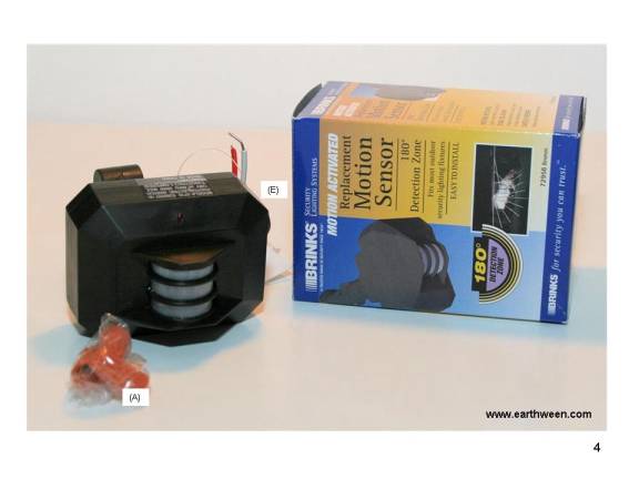
Figures 3 & 4 are views
of the same two sensors, contents removed from the box. Both sensors come with
3 electrical wire nuts.
Figure 3 depicts the Cooper
Lighting sensor that Menards carries. Cooper Lighting motion activated motion
sensor, model MS180 Bronze.
180 degree detection zone,
70 feet. 500 watts maximum load. Input, 120vac, 60hz.
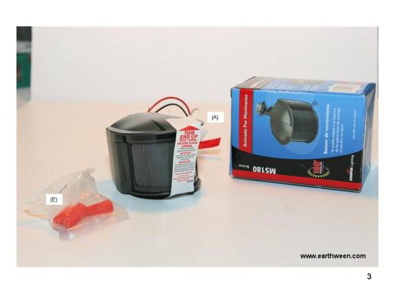
Figure 4 depicts the Brinks
sensor that Meijer carries. Brinks motion activated replacement motion sensor,
model 7295B Bronze.
180 degree detection zone.
300 watts maximum load. Input, 120vac, 60hz.
Construction Overview
The construction of the
control isnt that complicated. We basically connect the sensor to the outlet
box, cut the extension cord in two halves, connect the wires of the sensor to
the extension cord wires, put a cover on the outlet box, pretty much done.
All photos in the conduction
steps depict the Cooper Lighting sensor (as seen in Figure 3).
Step 1
Drilling a Hole in the
Outlet Box
If your outlet box has predrilled
hole, you can skip this step.
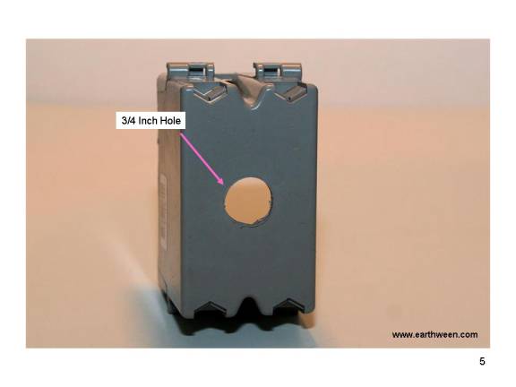
Drill a 3/4 hole in the
center of the back of the outlet box. Make sure the holes are dead center (see
Figure 2).
Step 2
Connecting the Sensor to
the Outlet Box
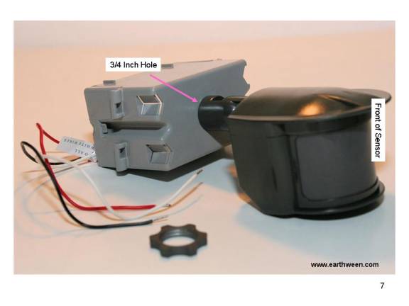
Unscrew the nut on the
sensors arm. Pass the three wires through the hole of the outlet box and screw
the arm of the sensor into the outlet box (Figure 6). The 3/4 inch hole will be
tight for sensors threads.

Figure 7 shows the sensor
completely screwed into the outlet box. Try to position the sensor (screw) so
that it ends up a horizontal position along with the outlet box as show in
Figure 7.
Step 3
Secure the Sensor to the Outlet Box
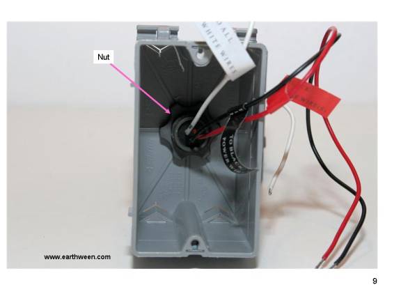
Pass the three wires inside
the outlet box through the nut of the sensor.
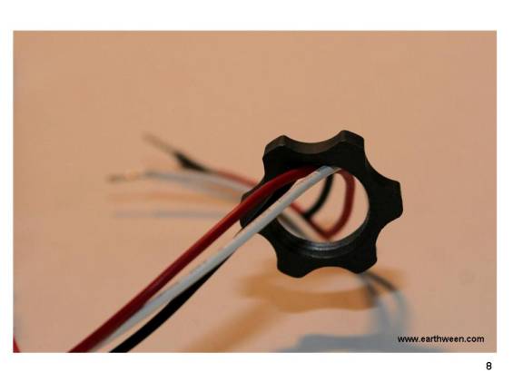
Screw the nut onto the
threads of the sensor arm until tight using your fingers only. No need to over
tighten the nut.
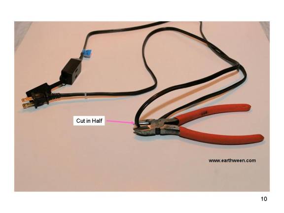
Step 4
Connect the Extension Cord
Cut the extension cord in
half using wire cutters as seen in Figure 10.
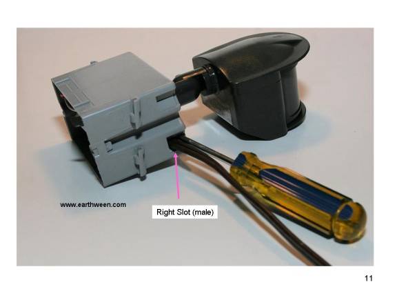
Using a Philips screw
driver, push the screw driver end through the outlet box slotted hole, bottom
hole, on the right side of the outlet box (right side when looking into the
open outlet box). The pass through the MALE end of the extension cord (the end
that was cut) into the outlet box as seen in Figure 11. It really doesnt
matter which end of the extension cord ends up in which slotted hole, but for
consistency, I will reference the MALE side and FEMALE sides of the outlet box.
These sides represent the side the male or female end of the extension cord was
inserted.
Remove the screw driver once
the extension cord wire is passed through the slotted hole. Then repeat the
steps with the FEMALE end (the end that was cut) on the left side of the
control (left side when looking into the open outlet box).
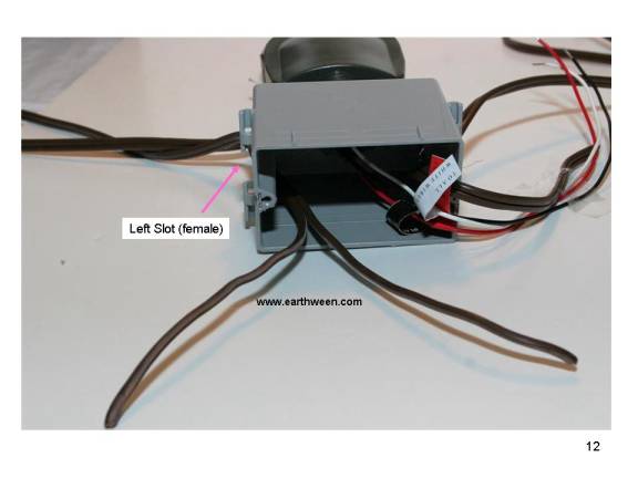
Make sure you pull enough of
the extension cord halves into the box; about 6-8 inches of slack. Now separate
each extension cord wire into its two halves. Figure 12 shows the left
extension cord split into its two halves.
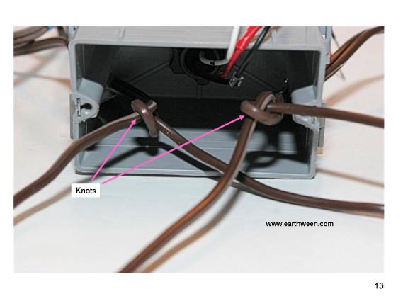
Tie a knot in both extension
cords, creating the knot as close to the inside of the outlet box as possible.
Then pull the other ends of the extension cords so that the knots are pulled
inside the outlet box, resting at the entrances of each slotted hole. These
knots will prevent/protect the extension cord wires from getting pulled out of
the outlet box.
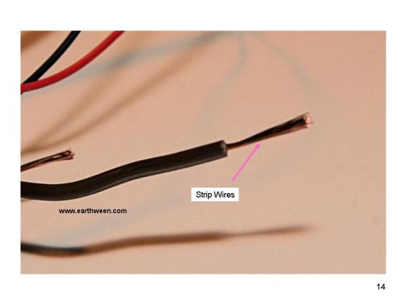
Now strip all 4 ends of the
extension cord wires leaving 1/2 inch of copper exposed as seen in Figure 14.
Step 5
Wire Connections
The sensor wires should be
pre-stripped of insulation at their ends. To insure a better connection, I
suggest stripping the ends a little more. Again,1/2 inch of copper should be
exposed.
The sensor directions
explain how to connect each of the sensors three wires to the wires of a light
fixture. Instead of connecting to a light fixture, we are going to connect the
wires to the ends of the extension cord.
Refer to Figure 15 for this
following instructions on connecting the wires.
When connecting wire, twist
wires together in a clockwise fashion then screw on the electrical wire nut
onto the wires also in a clockwise direction.
1. Connect the white (W)
sensor wire to one wire of the female (left) extension cord pair of wires and
one wire of the male (right) extension cord pair of wires.
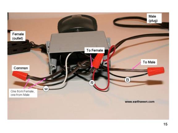
2. Connect the red (R)
sensor wire to the remaining female (left) extension cord pair of wires.
3. Connect the black (B)
sensor wire to the remaining male (right)
extension cord pair of wires.
4. Optional (not shown)
to
make the control a little more water proof, add a dap of clear silicon to the
inside of the wire nuts.
Step 6
Final Assembly
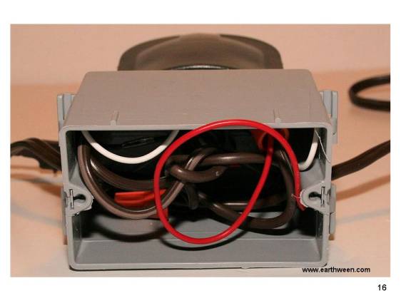
Tuck all wires into the
outlet housing as seen in Figure 16.
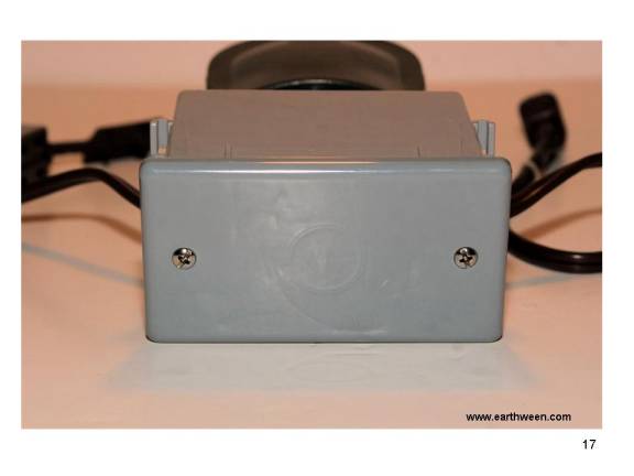
Attach the outlet cover as
seen in Figure 17.
Step 7
Cover the Light Sensor
Some sensors have a light
sensor to keep the control from activating in daylight (dusk to dawn setting).
Why turn on a light in daylight sort of thought. To insure this doesnt
become an issue in the control, we cover the light sensor with some black tape
as seen in Figure 18. We want our control to work in daylight, darkness or
anything in between. Read the instructions of the sensor to find out all
features, functions, deviations of your particular sensor.
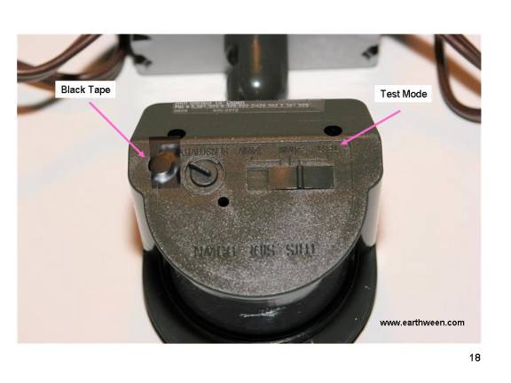
Most sensors have two
controls, one for sensitivity and one for activation time. Some sensors have
a test mode that allows the sensor to trip for a very short period of time,
4-10 seconds and then turn off and reset. These settings are ideal for
Halloween props, where we want the trigger to only last a moment. Read the
sensor manual for your sensor to get all of the details.
Testing
I suggest using a power
strip with a fuse and/or circuit breaker to prevent any possibility from
mis-wiring of the control.
1. Set the sensors
sensitivity to its maximum.
2. Set the sensors
activation time to test or its minimum.
3. Plug a lamp with a small
wattage blub; say 60 watts or less into the female (left side) of the control.
Then plug the sensor control into a live household outlet, giving the control
power.
Once you plug the control
into the outlet, the lamp should light for the specified duration of time.
Note: first time the sensor control is plugged in, there might extra time
applied to the activation upon first detection of motion. Read the instructions
of your sensor for exact behavior.
If your power strip trips a
breaker or blows a fuse, then you mis-wired something.
4. While the lamp is lit
(on), remain motionless and wait for the lamp to go out. The wave your hand in
front of the sensor. The lamp light should light up again. If it doesnt, then
you mis-wired something.
Trouble Shooting
1. First place to look is
the red/black wire connections. Is the wiring correct? Red wire should be
connected to one of the female (left) extension cord pair of wires. The black
wire should be connected to one of the male (right) extension cord pair of
wires.
2. Manual Override Feature.
Some sensors have a manual override feature that allows you to turn on
(activate) what is plugged into the control (our lamp) by giving and taking
away primary power to the control using a timing sequence like on, off for a
second, then on again. This feature could be causing your test scenario some
issues. Refer to your sensors manual for more information.