|
Switch Mat Control Project (Floor Mat) Last Update : 05/19/2009 Version : 1.3 This document contains notes to myself that allowed me to construct the switch mat control. Instructions within this document are notes to myself and recommend steps to myself. Anyone using this document to construct a switch mat control does so at their own risk. Beware; this document is intended only for people with electrical and electronic project skills and the knowledge of the involved hazards to property and to life forms including people, and the necessary safety procedures. Use the information here only at your own risk. The use of the switch mat control is at the user's sole risk. By purchasing the components to build the switch mat control, the purchaser/builder understands that the switch mat control is intended for educational purposes and any use of this information, components, or completed project is at the user’s own risk. The creator/supplier of this information and components shall not be liable for any damages or personal injury from the use of the switch mat control. The relay mentioned in this document is a mini relay with coil of 6VDC with rated contacts at 120VAC at 10A. Nothing exceeding these specifications should be used in the output of the control. The information contained in this document is not to be redistributed. Tools Required Note: not all tools may be required if some of the components have already been prepared. Pliers Phillips Screw Driver Black Tape Hot Glue Gun (+ glue) Soldering Iron (+ solder) (minimal soldering needed, 4 solder connections) Wire Strippers Wire Cutters Drill (w/ 3/4 inch drill bit)
Components - Supply List ($20) Reference Figure 1 for a picture of each component. Note: not all components will look exactly like what is pictured in this document. The power adaptor could be a different size, color, output voltage, etc. The relay could be slightly bigger, smaller, different color, make, voltage, etc. This goes for all of the components. (A) 2 – single outlet boxes (gang box, wall box) ($1) (B) 2 – outlets (duplex outlet) ($2) (C) 2 - outlet box covers ($1) (D) 1 - Power cord – 125VAC, 10amp ($1) (E) 1 - 6-9vdc Power adaptor (wall wart/transformer) ($2) (F) 1 - outlet connector ($1) (G) 1 - 6vdc relay rated for 120vac, 10amps ($1) (H) 1 – electrical wire nut (.50) (I) 5 pieces of misc wire (.50) (Z) 1 Alarm mat (switch mat) dimensions 21” x 14” ($8) 2 zip ties (not shown) (.50) Misc expense, glue, solder ($1.50) Prices are approximations. Power adaptor, power cord can be obtained via surplus, garage sale, Goodwill, etc. Adaptors from old cordless phone systems work perfectly. Alarm mat is the only purchase that is hard to make. Buy at Harbor Freight in store for $10, online for $7.99 at http://www.harborfreight.com/cpi/ctaf/displayitem.taf?Itemnumber=96481 Another reasonable option might be a Floor Mat Switch from Trossen Robotics. http://www.trossenrobotics.com/store/c/2754-Floor-Mat-Switches.aspx The 6vdc relays (rated for 120vac, 10amps) can be found at online electronics stores. Look here. Radio Shack - http://www.radioshack.com 7-9VDC/12A SPDT Relay, Mini ($4.49) http://www.radioshack.com/product/index.jsp?productId=2049716 Electronic Goldmine - http://www.goldmine-elec.com/ 9VDC 10Amp Contact SPST Relay by OEG ($1.25) http://www.goldmine-elec-products.com/prodinfo.asp?number=G1996 Fully enclosed relay by OEG type SDT-SS-109DM features 9VDC coil and SPST 10Amp 250VAC contacts. Size only 24mm (L) x 10mm(W) x 24mm(H). Has solder pins for PC mounting on bottom. Brand New. G1996 All Electronics - http://www.allelectronics.com/ 6VDC SPDT 10A RELAY ($1) http://www.allelectronics.com/make-a-store/item/RLY-501/6VDC-SPDT-10A-RELAY/1.html Fujitsu # FBR161NED006-WB. 6Vdc, 100 Ohm coil. S.P.D.T., 10 Amp contacts. 0.86" x 0.64" x 0.63" high sealed plastic case. PC leads. American Science & Surplus - http://www.sciplus.com/ Search ebay with the following "5V DC Relay 10A" 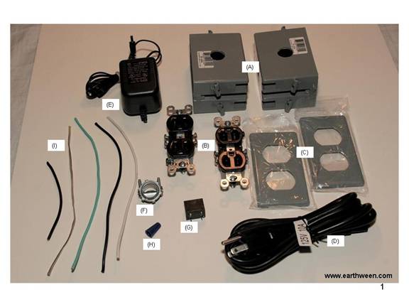
Construction Overview The construction of the control isn’t that complicated. We basically need to transfer AC power from our control to our prop when the mat is stepped on. We first need input power. One of the outlets (right) of our control will be supplied input power from the power cord. We will power our adaptor (wall wart) with this same input power. The other outlet (left) on our control will be our “output” power source. Output will be 120VAC, same as our input. We will get our output power from the input source, but only through the completed circuit made by our relay. We basically use the common and ground wires from our input outlet and connect them to the output outlet. We connect the hot (black) input power wire to the output terminal of the relay and the other terminal we connect to the output outlet. We connect the one wire (negative or positive) of the low voltage output of the adaptor to one of the inputs of the relay. We connect the other adaptor wire to one of the wires of the switch mat. The other wire of the switch mat is connected to the other input of the relay.
Step 1 Drilling Holes in the Outlet Boxes If your outlet boxes have predrilled holes, you can skip this step. Drill a 3/4 hole in the center of each outlet box. Make sure the holes are dead center (see Figure 2). Also make sure the holes are drilled on the sides of the outlet boxes that are flat/flush. The other side of the outlet has tabs which will impede the ability to screw the two outlet boxes together with the NM connector. 
Step 2 Connecting the Outlet Boxes Figure 3 depicts the two outlet boxes connected by a 3/8 NM connector. If your outlet boxes are already joined together, you can skip this step. Otherwise, unscrew the connector parts and insert the male (threaded) end of the connector through one of the holes of one of the outlet boxes from the inside. If needed, screw the connector until the threads show outside the outlet box. Then attach (screw) the other outlet box onto the threads of the exposed connector until at least one thread of the connect sticks through the inside of the second outlet box. You then should be able to screw the female (“nut”) of the connector onto the thread(s) inside the second box. 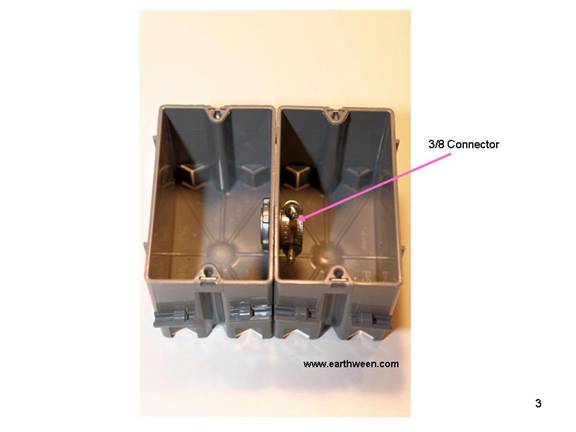
The connector is the only thing securing the two outlet boxes together. Make sure there is a tight bond between the two outlet boxes. Secure both outlet boxes with hot glue if desired. Variation Instead of using two single outlet boxes, you could use 1 double outlet (gang box). The reason that two outlet boxes are being used here is because you can find single outlet covers that fit snugly (without much overlap) over the boxes for single outlet boxes. Plus getting wires (and securing them) into the box is simpler with the slotted input holes of the plastic boxes. A duplex metal gang box is good alternative. However, the cost is $6 or more. You can find a metal double outlet cover that fits nicely over the box as well for about $1.25. You could also use two single metal outlet boxes as well. One of the advantages of the metal boxes is that they have connector holes already cut into the metal via metal knockouts. These knockouts are meant for the NM connectors. If you use a metal outlet box, you will need additional NM connectors to secure all of the wires (power, adaptor, speaker) into the box.
Step 3 Connecting the Power Cord You will need to cut the end off of the power cord, the female end (NOT the end that plugs into the wall). Cut the end off as close to the female plug as possible. This will give your control more power cord length. There are slotted holes in the outlet boxes. Use a screw driver and push through the slotted hole and then push through the power cord. You can choose to strip off some of the outside insulation of the power cord, exposing the 3 inner wires before or after the insertion of the power cord through the slotted hole. Figure 4 shows a screw driver assisting the power cord through the slotted hole of the right outlet box. 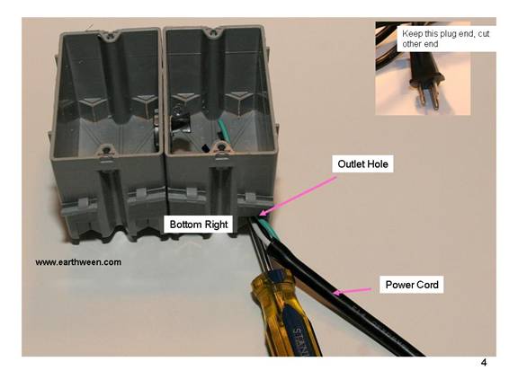
Figure 5 depicts another view of the power cord after it as been pushed through the slotted hole. 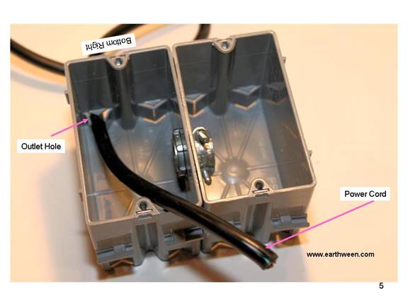
Once the power cord is inserted through the slotted hole of the outlet box, you need to strip off a 3 inch section of the black insulation of the power cord to expose the 3 wires inside. This needs to be done to properly size the length of the wire needed inside the outlet box. We don’t want too much extra wire inside the outlet box since we need to install the outlet inside the box. 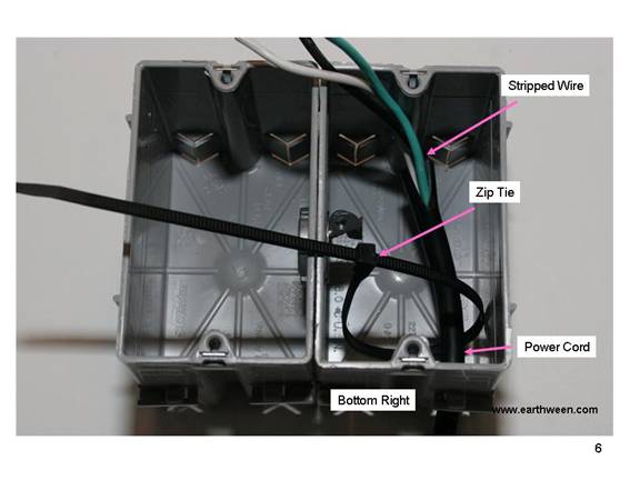
Make sure there are about 3 inches of the stripped (3 wires exposed) and 2 inches of the unstripped wire through the outlet box for a total of about 5 inches. Use the zip tie (Figure 6) and secure it around the black (unstripped) portion of the power cord and secure it tightly around the base of the cord where it enters the outlet box…inside of the box. 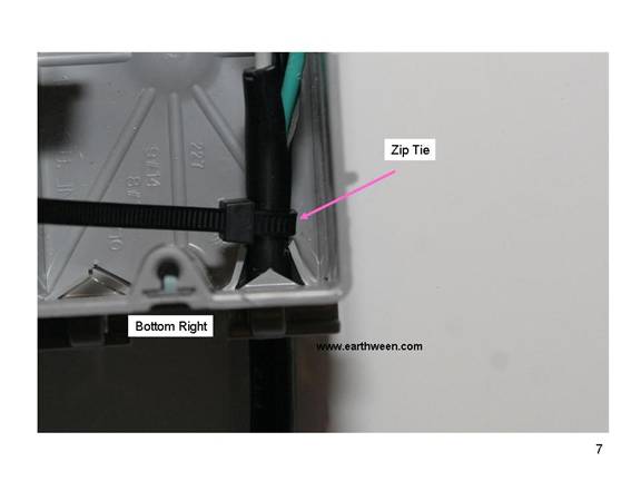
Securing the zip (Figure 7) tie will help prevent the power cord of getting pulled out of the outlet box. Cut the zip tie as need to remove the excess tie. Remember, we still need room to install the outlet inside the box.
Step 4 Connecting the Right Side Outlet The right outlet receives power from our power cord. We need to connect the three wires from the power cord to the outlet. On the bottom side of the outlet, there should be a notation that says “white wires”. The white wire is typically the common wire. The black wire is the “hot/live” wire and the green (or off color) is the ground. Make sure the white wire is connected to the correct side of the outlet and the ground wire is connected to the ground terminal (screw). The white wire screw is typically silver and the black wire screw is typically a brass color. You will need to strip about 1 inch of the insulation of each of the wires from the power cord using a wire stripper. Note: you will see some solder on the tips of the three wires in the pictures shown. Using some solder on the tips of the wires helps keep them together so that no stray copper strands become loose or exposed. When outside insulation of each wire is stripped and the copper wire is exposed, twist the copper wires in a clockwise fashion into a tight wind. Then, if desired, apply some solder to the tips of the copper wire to keep the strands together. When attaching each wire to the proper screw on the outlet, you will need to first loosen the screw in a counter clockwise turn. I suggest wrapping the wires around each screw of the outlet in a clockwise fashion. This helps keep the wire wrapped around the screw when the screw is tightened. Tighten each screw (terminal). 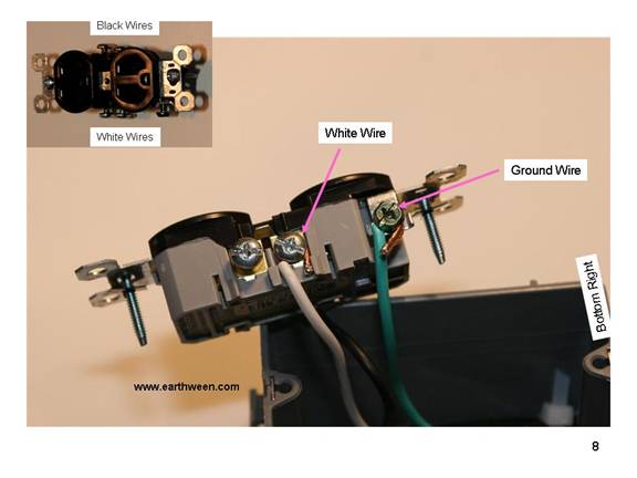
As shown in Figure 9, on the other side of the outlet, connect the black wire. 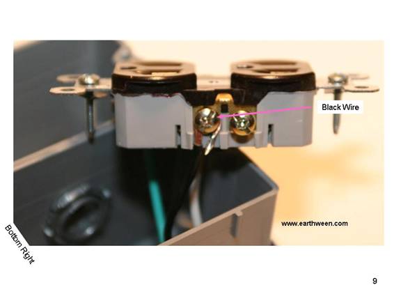
Step 5 Preparing Wire for the Left Side Outlet We need to carry the power from the right outlet to the left side of the outlet box, passing some wires through the connector hole in the center of each box. There are three single wires, one white, one black, and one green (or off color) that are about 8 inches long. Strip both ends of the white and green wires to expose about 1 inch of the copper wiring. Twist and solder if desired. Strip the end of the black wire at 1 inch and ¼ inch on the other side. The ¼ inch side will be soldered to the relay, so it needn’t be stripped as much as the end that connects to the outlet. On the right outlet, the one we already connected wire to…connect the white wire to the other white wire terminal (screw) on the outlet and the green wire to the ground terminal (screw). You will need to double up on the ground (green) terminal. Meaning, there isn’t another terminal for a second ground wire. You will need to unscrew the ground wire and connect both green wires to the terminal and re-screw both onto the outlet. 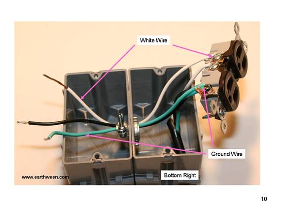
As seen in Figure 11, connect the black wire, the end that is striped to 1 inch of copper, to the black side of the outlet using the unused terminal (screw). Then pass all three wires through the center connector to the left side of the box as seen in Figure 10. 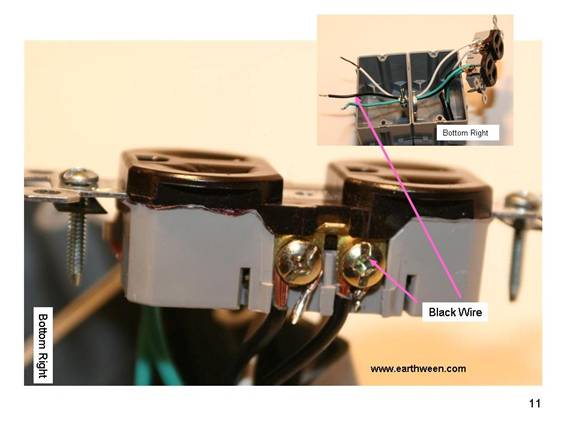
Step 6 Installing the Power Adaptor The power adaptor should take an input voltage of 110-125VAC and output 6-9VDC around a 500ma. The low voltage DC power will be used to trigger a relay that will complete the AC circuit to pass AC power from the input outlet (right) to the output outlet (left). Cut the power adaptor wire, leaving about 12 inches of wire. Thread the wire through the outlet box slotted hole, same one the power cord is running though. Use the small zip tie to secure the adaptor wire to the power cord inside the outlet box. Leave enough of the adaptor wire (enough slack) to allow the adaptor to plug into the top of the right outlet once mounted. Three inches should do. See Figure 14. 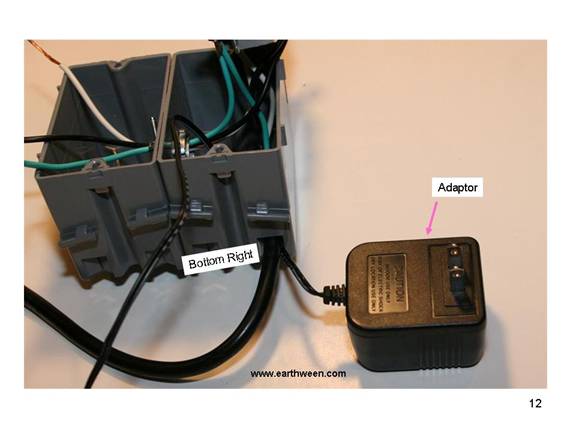
Thread the adaptor wire through the connector hole in the center of the outlet boxes, taking it to the left outlet box as seen in Figure 13. 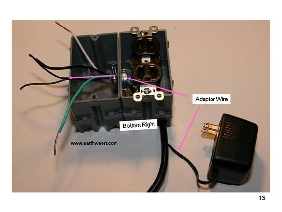
Mount (screw) the outlet to the outlet box, secure the outlet cover and plug in the adaptor as seen in Figure 14. 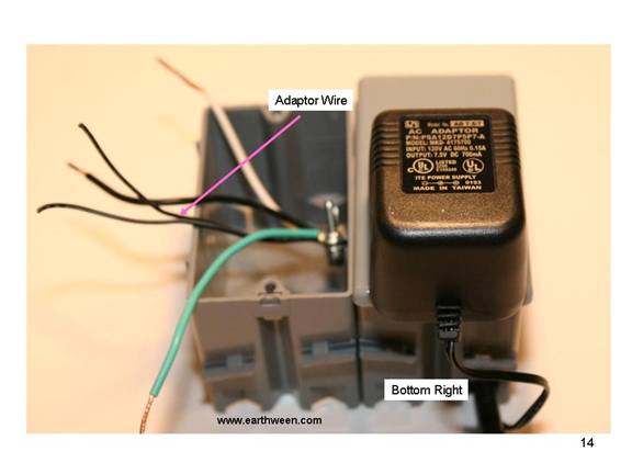
Step 7 Connecting the Left Outlet Using the wires that were fed through from the right outlet box, connect some of these wires to the right outlet. Notice that the outlet depicted in Figure 15 has the outlet twisted showing white/ground terminals facing the right side. This is just to show the connections. When secured to the outlet box, the actual outlet will be turned so that the white/ground terminals are facing to the outside. Connect the white wire from the right outlet to the white terminal screw as seen in Figure 15. Also connect the green wire from the right outlet to the ground terminal on the outlet. The white wire screw is typically silver and the black wire screw is typically a brass color. 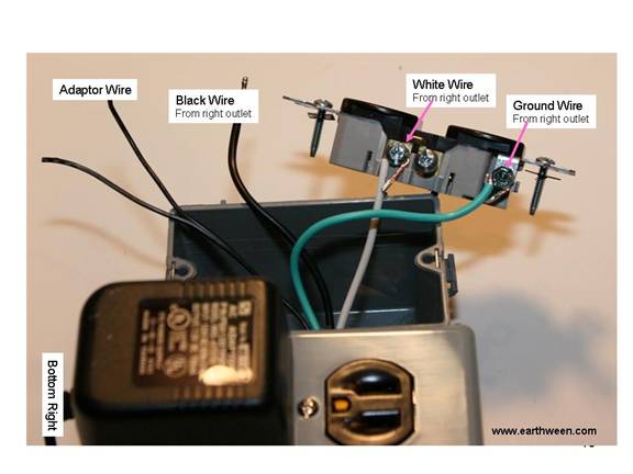
Turning over the outlet, connect a 4 inch (short) black wire to the black (hot) side terminal. You should strip the black wire on one end to expose 1 inch of copper and on the other end expose ¼ inch of copper wire. Twist and solder both ends if desired. Connect the 1 inch side of the wire to the “hot” side of the outlet as seen in Figure 16. DO NOT connect the black wire from the right side outlet at this time… it will get connected to the relay later.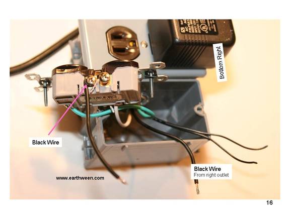
Step 8 Installing the Speaker Wire For the lack of a better description, we need to install some speaker wire that will eventually connect to the wire running to the switch mat. Any wire could have been used, but speaker wire is the right size for the job. The speaker wire will help complete the circuit for the direct current (6VDC) loop from the adaptor through the switch mat to the relay that will complete the AC circuit from the right outlet power to the left outlet. Insert the 8 inch speaker wire into the left outlet slotted hole as seen in Figure 17. I would choose the right slot on the left outlet box. 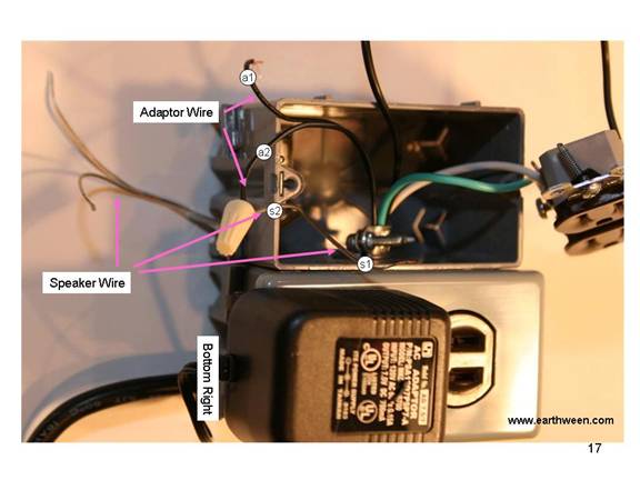
Once the wire is inside the left outlet box, split the wire into its two halves and tie a knot in the speaker wire to prevent it from getting pulled back through the slotted hole…similar concept to the zip tie method securing the power cord/adaptor wire in previous steps. Just make sure the wire can be pulled back through the outlet box. Strip the ends of the speaker wire inside the left outlet box and the ends of the adaptor wire also in the left outlet box. Twist one of the adaptor wires and one of the speaker wires together in a clockwise fashion and secure with the electrical nut, again twisting in a clockwise direction. In Figure 17, a2 and s2 represent an adaptor wire and the speaker wire respectively joined. Wires a1 and s2 are left “unmarried” at this time. They will be soldered to the relay later.
Step 9 Installing the Relay The relay installation is probably the most complicated part of the construction process. Only because there is some soldering involved that can be tedious since the relay is meant for a printed circuit board installation and we are doing a direct wire solder. 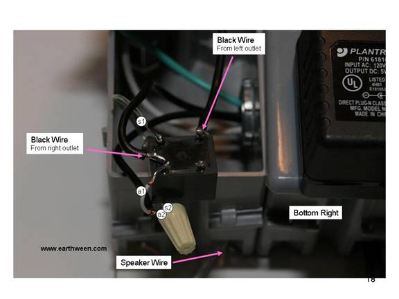
Figure 18 depicts a Single Pole Double Throw Relay (SPDT). Basically the end with the 3 prongs is soldered first. The two outside prongs (top/bottom) in the corners take the input voltage (6VDC). We solder the remaining speaker wire (s1) and the remaining adaptor wire (a1) to each of the corner prongs, in no particular fashion (doesn’t matter which wire ends up on which prong).
The black wire from the right outlet is soldered to the middle prong on the three prong side. And finally the black wire (short one) from the left outlet is soldered to the top corner prong (important that you solder to this prong, the normally open prong) as seen in Figures 18 and 19. 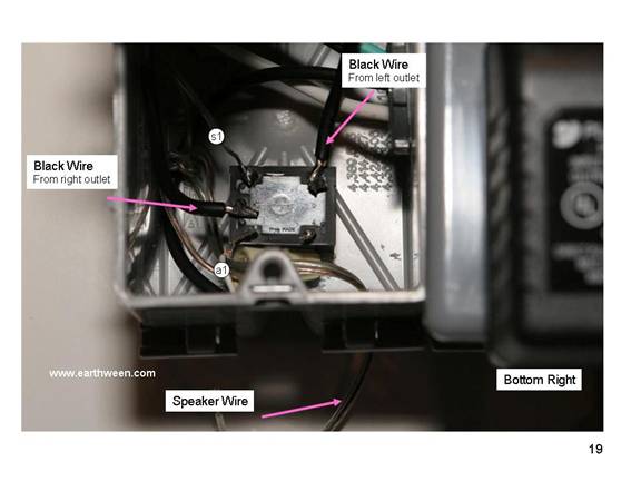
Secure the relay to the bottom of the left outlet box as seen in Figure 19. Just place a dap of hot glue on the bottom of the relay and secure to the bottom of the left outlet box.
The following diagram depicts another view of the relay. The relay pictured is actually a different “brand/vendor” of SPDT relay, but functions exactly the same. Notice that we only use 4 of the 5 pins/prongs. 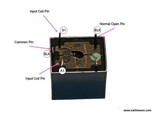
As a precautionary step, it is a good idea to cover the relay and connections with some hot glue (Figure 20). This will not only help insulate the connections from other connections installed in the outlet box, but will help secure the solder connections from being broken. It is important that all of your connections are secure before covering with hot glue. It is probably a good idea to test the control (later in this document) before actually using the hot glue. You can skip the glue step and revisit it after you are satisfied the control works. 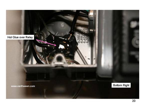
Figure 21 shows the left outlet being installed in the left outlet box, properly (ground holes down) with the white/ground wires on the left side.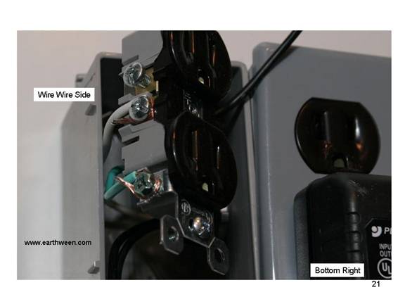
Figure 22 depicts the control with the outlet cover placed on the left side.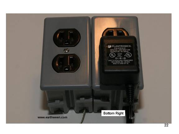
Step 10 Connecting the Switch Mat The switch mat is a store bought product that is sold as an Alarm mat (Figure 24). The mat itself is made from a light weight material with a foam padding and a plastic cover. Inside the mat are some “metal” type connections that make contact, when the mat is stepped on (pressure is applied) with a common metal conductor. When the two contacts meet, an electrical circuit is completed and low voltage DC power can flow through the contacts. When pressure is removed from the mat (someone steps off the mat), the contacts separate (do to the foam padding) and the electrical circuit is broken. 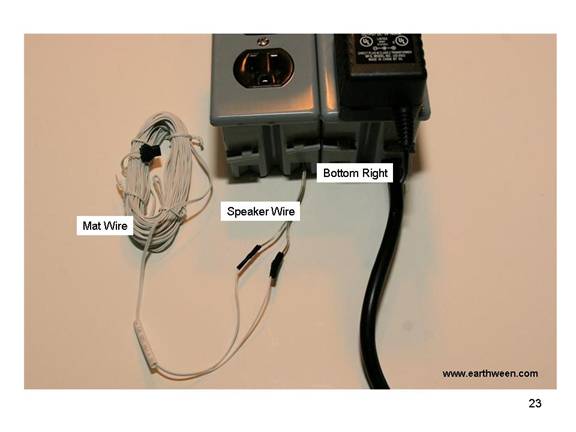
Next connect mat wire to the speaker wire. Using the end without the black connector, separate the mat wire into its two halves and the speaker wire into its two halves and strip and join each wire to the other, mat wire to speaker wire as seen in Figure 23. Twist the copper wires together securely and tape the wire joins using black electrical tape. 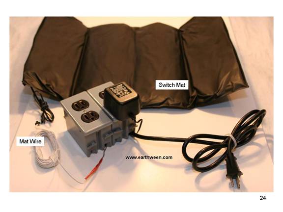
As a the final step, the mat is joined to the mat wire using the preinstalled black connector. Make the connection and prepare to test the control.
Testing I suggest using a power strip with a fuse and/or circuit breaker to prevent any possibility from mis-wiring of the control. 1. Make sure the power adaptor is plugged into the right side outlet. 2. First plug a lamp with a small wattage blub, say 60 watts or less into the right side of the control, above the power adaptor. Make sure the lamp is switch is on. Then plug the mat control into a live household outlet, giving the control power. If your power strip trips a breaker or blows a fuse, then you mis-wired something. If the lamp lights, this demonstrates that the right side of your control is receiving power. 3. Now unplug the control. 4. Next, unplug the lamp from the right side of the control and plug it into the left side of the control. Plug in the control into a live household outlet again. If your power strip trips a breaker or blows a fuse, then you mis-wired something. Otherwise, you are good to test the switch mat. 5. Apply pressure to the mat until the (you should be able to hear the magnetic switch trip) lamp lights. The lamp should light when approximately 2 pounds of pressure is applied to the mat and should go out when pressure is removed from the mat. If this sequence of events is working, then congratulations, you have successfully created a switch mat control. If your power strip trips a breaker or blows a fuse, then you mis-wired something. Trouble Shooting 1. First place to look is the relay wiring. Is the wiring correct? 2. Is the switch mat working? To test, unconnected the wires from the matt to the speaker wires. You should be able to do the same tests without the use of the mat. In this test, connect the two speaker wires together to simulate the mat being stepped on. Connect the wires before trying any testing steps then attempt tests 4 & 5. The lamp should light with the control is plugged in (not when the mat has pressure…in this test the mat is not involved in the test). If the lamp lights, then your connection to the mat is not correct or the mat is defective.
|