|
Time Delay Relay Control Last Update : 01/15/2011 Version : 1.0 This document contains notes to myself that allowed me to construct the time delay relay control. Instructions within this document are notes to myself and recommend steps to myself. Anyone using this document to construct a time delay relay control does so at their own risk. Beware; this document is intended only for people with electrical and electronic project skills and the knowledge of the involved hazards to property and to life forms including people, and the necessary safety procedures. Use the information here only at your own risk. The use of the time delay relay control is at the user's sole risk. By purchasing the components to build such a control, the purchaser/builder understands that the control is intended for educational purposes and any use of this information, components, or completed project is at the user’s own risk. The creator/supplier of this information and components shall not be liable for any damages or personal injury from the use of the switch mat control. The information contained in this document is not to be redistributed. Tools Required Solder Iron and Solder Wire strippers Wire cutters Black Tape Glue Gun (optional) Components - Supply List 1 - 120 VAC time delay relay 2 - six foot house hold extension cords Figure 1 depicts a typical industrial time delay relay. This is an 8 pin (octal) DPDT relay supporting a 10amp output. Input is 120 VAC. The delay is adjustable from .2 to 10 seconds. This relay is a perfect fit for our project. These relays are listed all over Ebay. When industrial machines are scaped, workers tend to dismantal the machines for parts and these parts are often sold on Ebay as used parts. You defiantly want to find used time delay relays. New ones are upwards $80. If you are lucky, you can find a lot of used relays and get them for $5, $10 a piece. 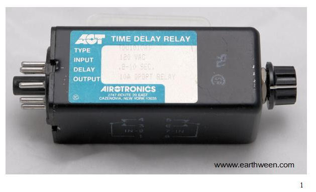
Figure 2 shows the top and the bottom of the relay. Notice the 8 pins in the right picture. This is a standard octal relay that fits into a standard base for industrial machines. Each pin is important and has a purpose in the circuitry of the relay. 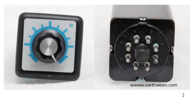
Figure 2 shows the circuitry layout of the relay. Most all relays of this sort have some sort of diagram of the “switching” nature of the relay and the open and closed circuits when the relay coil is energized and not. 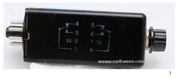
As the diagram notes, this is a DPDT (Double Pole Double Throw) relay. For our purposes, we really only need a SPST – Single Pole Single Throw relay, so we are going to inore one half of the relay (pins 5, 7, and 8). See diagram below. 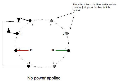
Step 1 I like to cut (remove) the three pins that aren’t used in the control. I use wire cutters to snip pins 5, 6 and 8. Figure 4 depicts the relay with the cut poles (hard to see). In the diagram below, we see where input power is applied. Based on the schematic of the relay, we know it takes 120 VAC power and the relay is triggered by applying this power to pins 2 and 7. 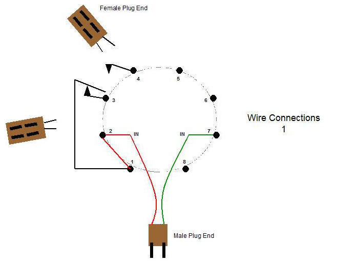
Step 2 Pin 1 is going to be one side of the circuit that we need to get power to in order to power the ends of the extension cords. We need to provide power to pin 1 since it is involved in our “complete” circuit round trip (when involved with either pin 3 or pin 4). Bind pins 1 and 2 together. Strip off some bare wire from the excess wire from the extension cords you cut or will cut in Step 3 or use some other excess wire. Wrap pins 1 and 2 together and use some solder to secure the wires to the pins so that they won’t ever get dislodged. See Figure 5. 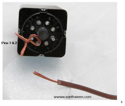
Figure 5 shows pins 1 and 2 bound and soldered. 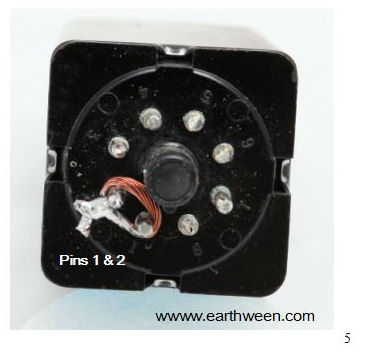
Step 3 Cut your extensions cords to the desired length. In the photos, I used a shorten length to demonstrate the technique. You really don’t need a lot of length since the control usually sits in-between a prop and another trigger control. I would work with a smaller length for the first control you attempt to build. You will need the male end of one extension cord and both female ends of both cords. Cut the cords at about the 12” inch length and split. Each wire end should now have two wires. Strip all ends with a wire stripper. Figure 6 shows the extensions cords cut, stripped, and ready to go. 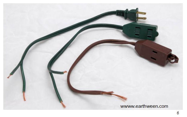
The complete circuit diagram we are trying to accomplish is shown in the next diagram. The green lines depict the “common” wire that goes from the input to both outputs. The red lines depict the “hot” wire that is needed to complete the circuit(s). 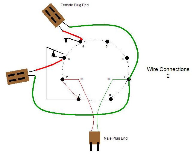
Step 4 Take a single wire from each of the 3 cords and twist them together. This will be the “common” wire for all circuits. Apply some solder to these twisted wires and prepare to solder these three wires to pin 7 of the control. I suggest soldering the wires in a vertical position so that the length of the three twisted (soldered) wires is parallel with the length of the pin. Apply solder and ensure you have a good solid connection (won’t break off). Make sure the soldered connection doesn’t touch another pin. Figure 7 shows the completed task. 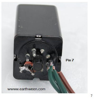
Step 5 Take the reaming loose end wire of the male cord and apply some solder to the stripped wire end. Then prepare to solder the wire to pin 2 of the control. Remember, pin 2 is already bound to pin 1 with some wire and solder. Attempt to solder the wire to pin 2 in a vertical position as previously described (for pin 7). Ensure the connection is solid and doesn’t make contact with pin 3. Figure 8 shows the completed task. 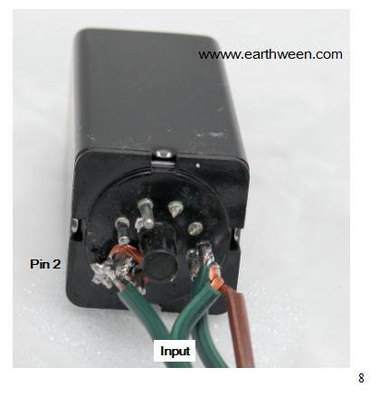
Step 6 Now take the remaining loose end wire of one of the female cords and apply some solder to the stripped wire end. Then prepare to solder the wire to pin 3 of the control. Again, solder in a vertical position and make sure it is secure and doesn’t make contact with other pins. 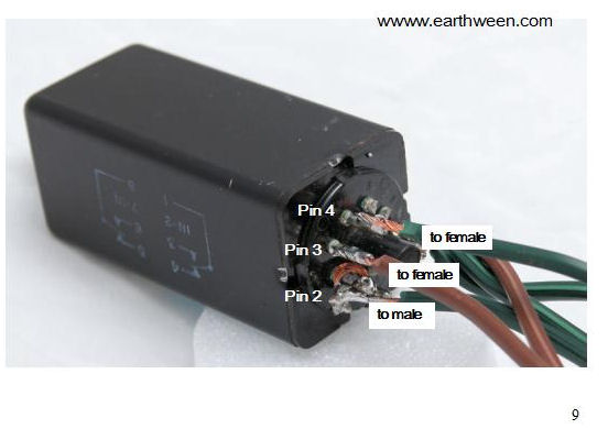
Repeat the solder connection for the last remaining loose wire end (from the other female). Solder the wire to pin 4 of the control, again, in a vertical position, securely and free from contact with other pins. Figure 9 shows the three connections soldered to the appropriate relay pins. Step 6 - Testing It is a good idea to test your control before continuing. However, testing the control in this state is dangerous. Make sure none of the control pins (with solder connections) is touching another (with the exception of pins 1 & 2). Beware; this step is only for people with electrical and electronic project skills and the knowledge of the involved hazards to property and to life forms including people, and the necessary safety procedures. Use the information here at your own risk. Be prepared In a bad case scenario, your power strip circuit breaker will trip or even worst, your household circuit breaker (or fuse) will trip (or blow in the case of a fuse). Don’t panic; just be prepared to reset the circuit breaker (or replace a fuse). Know where your circuit breaker box is and make sure you have a flash light in the case you loose light in the room where the circuit breaker box is located. Now on to the test Plug in a small lamp into one of the female ends of the control. I suggest plugging into the female cord connected to pin 4. We know when the control powers up, this female end should have power initially. Make sure the lamp switch is in the ON position for this test. Set the timer dial (if your relay has adjustable time delay) to something short, say 5 seconds. Then plug in the control (male end) into a live power source. I suggest using a power strip with some sort of circuit protection (breaker). I would turn the power strip off and plug in the control. Then, when ready, flip the switch of the power strip. If things are working, the lamp should light up. After 5 seconds, the lamp should shut off and remain off. To test the other behavior, turn off the power strip and change the lamp from being plugged into the female end connected to pin 3. In this configuration, when the control receives power, the lamp should NOT turn on until the elapsed time expires. Perform the test by flipping the switch on the power strip and take notice, after 5 seconds, the lamp turns on and stays on. Other problems Not all relays are made to operate in the same manner. Some relays have different input (coil) requirements. Some are 24 DC, some are 24 AC, this document and information assumes you are working with a 120 AC coil. The nice thing about working with this type of relay is that we can use the input power that triggers the relay to power our output devices using 120 AC power. Step 7 - Final Assembly After successful testing has been accomplished, you should do something to cover and protect your wire and connections. I like to use a hot glue gun and melt the glue into and around the connections. I use black tape and form a repository “lip” around the base of the relay….creating an area for the hot glue to fill around the base of the wires and connections 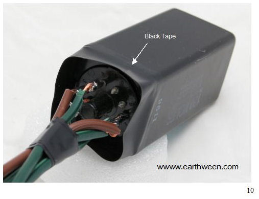
I hang the relay control from the wires and fill in the areas with a good portion of glue (1 to 2 sticks). See figure 11 for a good view of the glue and coverage of the bare wires and pins. 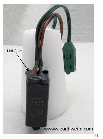
Congratulations, you just created a time delay relay control for use in your haunt.
|