|
Flying Crank Ghost (FCG) - Halloween Prop
|
|
|
|
07/01/2000
|
|

|
|
|
|
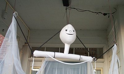
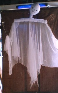
This is the Flying Crank Ghost I built for Halloween 2000. No metal was used in the frame. Just 2 small
pieces of 2x4 and 2 pieces of 1x2 wood to form a 'T' frame. Instead of using wire clothes hangers for the arms, I used wooden doll rods and formed 'joints' by tying
pieces together with wire.
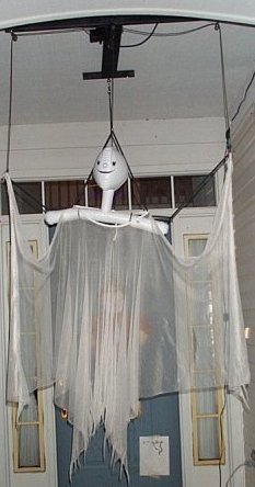
The body of the ghost was purchased and included a blowup ghost head and a cheese cloth body. For added effect, I
highlighted the cheese cloth with 'glow in the dark' hair spray. A black light was shown on the face of the FCG at night. The FCG ran outside, at the front entrance of
the house under the front porch. The FCG ran from dusk until dawn each night from October 1st until the 31st without any problems.
|
|
|
|
The Flying Crank Ghost (FCG)! What a marvel One of the best Halloween investment that can be made! Now, maybe cheaper...for some...
Doug Ferguson, the originator has started a phenomenon that has Halloween enthusiasts screaming for one. For
the original and source of the FCG, see the Phantasmechanics site.
My adaptation and/or version of the FCG doesn't stray much from the original, with the exception of maybe the expense.
The most expensive piece of the FCG prop is the motor. The most common motor is a Dayton series gear
motor, model 2Z806 (6 RPM) costing $50+ from Gainger or another industrial supply company. Last year I purchased a cheaper Dayton gear motor, model 3M096, which is a 7 RPM motor with a shorter shaft, for $35+ from Gainger .
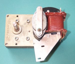
I've search the surplus sites over and over for a cheaper alternative and I think I have found one. Figure 1-1 is a
scan from a surplus catalog that has a pretty cheap gear motor. The only question was the torque, the quality, and the position of the motor vs the shaft and getting it to work for a FCG.
After the purchase and some testing, I have found all three to be satisfied.
|
|
|
|
|
|
Figure 1-1
|
|
|
|
The motor can be purchase at "The Surplus Center", phone 1-800-488-3407. I purchased 4 motors and paid just under $50 for
all, including S&H. They told me that they have approximately 130+ motors in their inventory. Better hurry before they run out. Unfortunately, I don't get a commission.
|
|
|
|
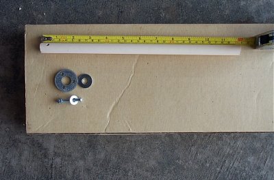
Parts needed
1 - 1/2 " OD CPVC pipe (4' in length)
1 - 1/2" OD 90 degree fitting
PVC Cement
1 - Household extension cord
1 - Size 8d 2" long nail or coat hanger
7/8 drill Bit
7/16 drill Bit
2 - 4' doll rod (for ghost)
1 - 24" 2x4
1 - 40" 1 x 2
2 - eye bolts with nuts
1 - eye bolt, screw in type
3 - small pulleys (optional)
5 - Size 8/32 machine bolts, 1 1/2" in length
1 - 1 1/2" Washer
Spring
1 - Merkl Korff motor
Power Drill
Hand Saw
|
|
|
|
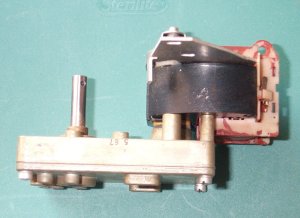
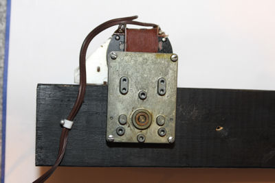
Some photographs of the motor are shown in Figures 1-2 and 1-3.
|
|
|
|
|
|
|
|
Figure 1-2
|
Figure 1-3
|
|
|
|
|
|
Regrettably, the motor isn't the same high quality as the Dayton series. You somewhat pay for what you get. Motor performance is
good, see the testing note below. The torque is somewhat lacking, but for heavier marionettes, using the counter weight method should work well.
Notice the small hole in the shaft. This is the key to the motor's use. Since the orientation of the motor to the shaft makes it difficult
to attach a crank to the shaft and have it rotate freely, we simply have to extend the shaft to clear the motor. We could use several different types of pipe or tubing, but to keep the
motor turning without too much stress, I choose to use PVC pipe. The pipe also is used as the crank. See pictures below for the general idea.
Testing: I tested the motor attached to a 1 lb marionette by running it continuously for 24 hours. The motor, although somewhat noisy, ran
flawlessly as well as the crank and other components.
|
|
|
|
|
|
|
|
Figure 1-3
|
Figure 1-4
|
|
|
|
|
|
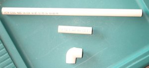
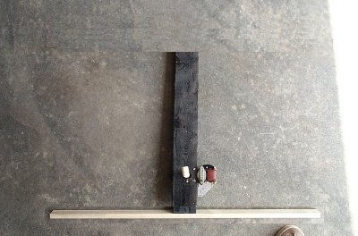
Figure 1-3 depicts the PVC pipe need for the arm of the crank. The PVC pipe I used is actually CPVC pipe and has an outer diameter
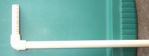
(OD) of 1/2". You should be able to find the PVC piping at your local hardware store. When the crank is assembled, it will look like Figure 1-4. However, don't assemble the crank until after
you have fitted the smaller piece around the motor's shaft and mounted the motor. You will need PVC cement for the final assembly.
The longest section of the crank is 12" (1 foot). The 90 degree right angle is purchased along with the pipe. The shorter piece of pipe is 3 1/4" long.
This piece will be secured to the motor's shaft.
|
|
|
|
|
|
|
|
Figure 1-5
|
Figure 1-6
|
|
|
|
|
|
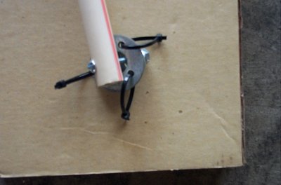
Figure 1-5 depicts a close-up of the smaller PVC pipe being connected to the motor's shaft. Don't permanently attach the pipe
to the shaft at this time. We need to mount the motor before doing that. These pictures simply demonstrate fitting needed. To secure the pipe, I used a 8d size nail, approximately 2" in
length. I drilled a small hole through the PVC pipe at about 1 1/8" from the bottom of the pipe. I then tested that I could cleanly insert the nail through the pipe and through the crank shaft and
out the other side of the pipe. When installed, the nail is bent to secure its place in the assembly. Don't do anything more than test your fittings at this time. We still have to mount the motor.
|
|
|
|
|
|
|
|
Figure 1-7
|
Figure 1-8
|
|
|
|
|
|
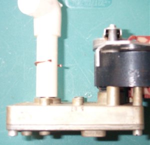
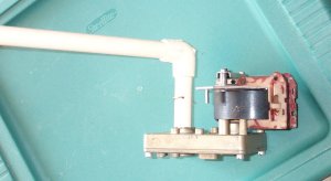
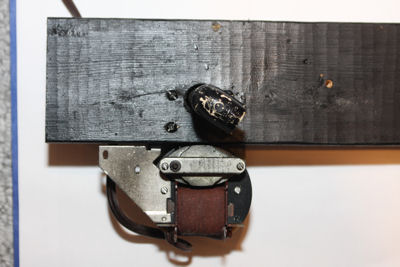
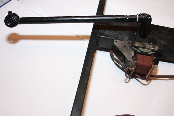
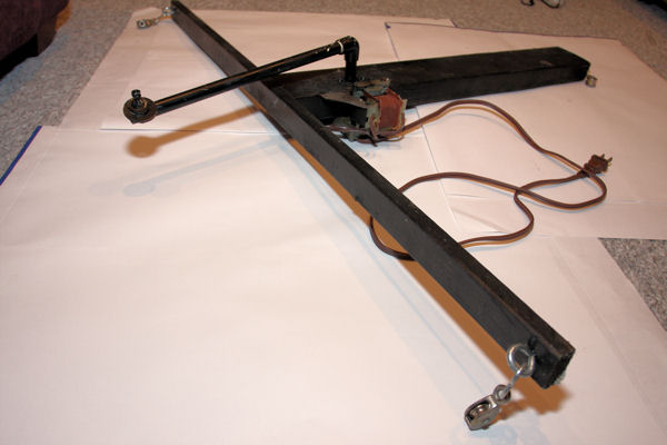
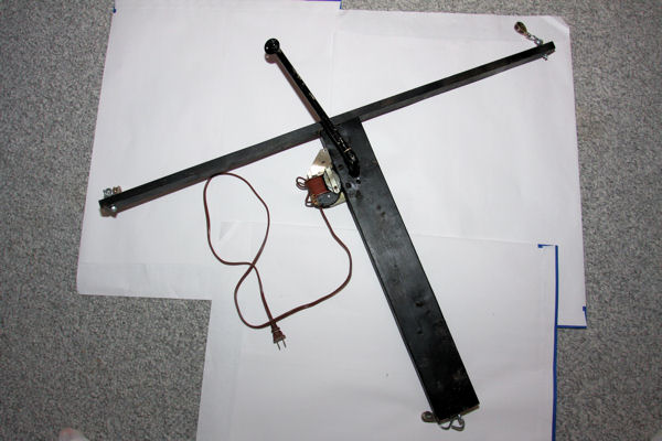
Figure 1-7 depicts the motor already mounted and the PVC pipe and crank already fitted. You will find more pictures and more
instructions on the next page. Figure 1-8 is a close-up of the end of the crank, with strings attached. Continue to the next pages for more recent pictures and instructions.
|
|
|
|
Here Are some more pictures of another FCG I built using the same materials, similar process, better pictures.
|
|
|
|
|
|
Figure 2-1
|
|
|
|
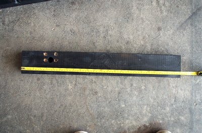
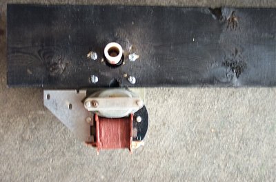
Figure 1-2 depicts the 24" 2x4 piece of wood that the motor is mounted in. Approximately 5" from the end of the board, a 7/8" hole
is drilled through the board. To help locate the proper location, the center of the hole is about 1 1/2" inches from the side (long side) of the board. Using these two measurements, you should hit
the bullseye.
|
|
|
|
|
|
Figure 2-2
|
|
|
|
Figure 2-2 depicts the same board with all of the holes drilled. After drilling out the larger center hole, place the motor shaft into the hole
and press firmly one the motor so that the bolt eyes make an indentation on the wood. Make sure the motor shaft is centered before making the indentations. The side of the motor should somewhat
flush with the edge of the board.
Remove the motor and you should have your markings for the 4 holes needed for the mounting of the motor. Use a 8/32" drill bit and drill out the 4
holes needed. After making all of the holes, change to a 7/16" drill bit and counter sink the holes about 1/8". Reinsert the motor and see if it fits flush with the wood. Figure 2-4 shows a
good picture of a motor flush with the 2x4.
|
|
|
|
|
|
Figure 2-3
|
|
|
|
Figure 2-3 shows a similar picture that the previous page described. Again, we use a 3 1/4" piece of 1/2" OD CPVC pipe and drill a hole
though it about 1 1/8" from the bottom of the pipe. Using a 8d 2" nail or coat hanger wire, secure the pipe to the shaft. Make sure you bend the nail or hanger so that it will clear the
diameter of the hole in the 2x4. You dont want the nail rub the inside of the hole when the motor turns the shaft.
|
|
|
|
|
|
Figure 2-4
|
|
|
|
Mount the motor as shown in Figure 2-4 and 2-5. Use 8/32 size bolts, 1 1/2" long to secure the motor to the 2x4. Figure 2-6 shows a good
example of the motor mounted to the board.
|
|
|
|
|
|
Figure 2-5
|
|
|
|
Pictures in Figure 2-5 and 2-6 show the motor mounted to the 2x4. Note that the CPVC shaft doesnt have the elbow for the arm attached at this point in time.
|
|
|
|
|
|
Figure 2-6
|
|
|
|
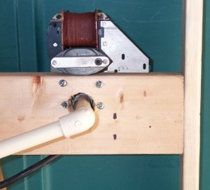
Eventually, you are going to want to power your motor to make sure the shaft clears the sides of the hole and that the shaft turns without issue. The motor has two
terminals. I cut a house hold extension cord off at the end closest to the female plug and striped the ends of the wires. I soldered the ends to the two terminals of the motor. Since we are working with
AC power, it doesnt matter which cord end is connected to which terminal. I secured the extension cord wire to the 2x4 with a cable wire clip.
You can plug in the extension cord and determine the
state of your motor. You definitely want to do this step before attaching the elbow to the shaft in the next step.
|
|
|
|
|
|
Figure 2-7
|
|
|
|
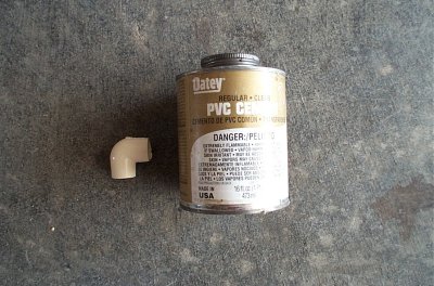
Next, you are going to want to cap the end of the shaft with an elbow. Using PVC Cement (shown in Figure 2-8), you can glue the elbow to the shaft. Make sure you are
happy with your motor mount before gluing the elbow onto the shaft. Once glued, you wont be able to detach the motor mount.
|
|
|
|
|
|
Figure 2-8
|
|
|
|
Figure 2-9 depcits the elbow attached to the shaft.
|
|
|
|
|
|
Figure 2-9
|
|
|
|
Once the motor is mounted, you can continue building the frame. Picture 2-8 shows a 1x2 about 40" long attached to the 2x4. I simply used
screws to secure the two pieces of wood.
|
|
|
|
|
|
Figure 2-10
|
|
|
|
Figure 2-11 depicts the crank are attached to the elbow. There is more detail on constructing the crank arm later on this page.
|
|
|
|
|
|
Figure 2-11
|
|
|
|
The ghost for my FCG was a store bought inflatable as seen in Figure 3-1. The ghost is light weight and comes with some cheese cloth that I sprayed with glow in the
dark hair spray which reacts under black light really well.
|
|
|
|
|
|
Figure 3-1
|
|
|
|
Figure 3-2 depicts connecting the ghost frame to the crank arm.
|
|
|
|
|
|
Figure 3-2
|
|
|
|
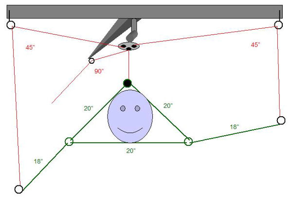
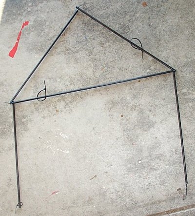
The ghost frame is made out of 1/4" wooden doll rod. The head of the ghost is sandwiched inside a triangle of doll rods, each
20" long. The arms are a little shorter, 18" each. I used plastic ties to join the doll rods by drilling 1/8" holes through the ends of each rod and fastening each end to end using the
plastic fastener. Wire or string can also be used. Where the arms connect to the triangle, make sure the joint is flexible so that the arms can move freely.
|
|
|
|
|
|
Figure 4-1
|
|
|
|
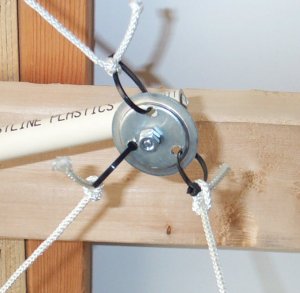
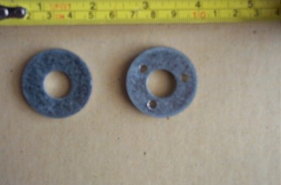
Connected to the end of the crank shaft is a large washer. The washer has three holes drilled into it (Figure 4-2). Using 1/8" thick string or rope, connect two
45" pieces of rope from the washer to the arms. The string should be tied to the washer and then fed though the eye hooks (or pulleys) at the ends on the motor frame and onto each arm, tied to the
end. Again, drill through the end of the doll rod and tie the rope to each end.
|
|
|
|
|
|
Figure 4-2
|
|
|
|
|
|
Figure 4-3
|
|
|
|
|
|
Figure 4-4
|
|
|
|
The third piece of rope to the third hole on the washer. Feed the rope down through to the top of the triangle of the ghost head. However, don't tie it to the top
of the frame, feed it through a loop that is connected to the triangle using a wire loop or fastener. Continue feeding the rope onto the back end of the motor frame through the eye hook or pulley.
The rope should be fed through the pulley and connected to either your counter weight (only needed if the ghost weights more that what your motor can handle) or secure to something. You should be able to adjust the height of the ghost using this last rope.
|
|
|
|
|
|
Figure 4-5
|
|
|
|
|
|
|
|
|
|
|
|
|
|
|